An IP67 aluminum enclosure is a system of five sealing interfaces working together: the cover gasket groove, the cover interface and its stiffness, the fastener layout, the cable entry, and the assembly tolerances that hold all of them. Each one is an engineering decision with a measurable dimension — groove depth, panel thickness, screw pitch, gland size, machining tolerance — and a design that ignores any one of them fails the IP67 immersion test even when the other four are perfect. This guide walks through the complete design sequence, with the numbers that make each interface work.
What IP67 Actually Requires
Under IEC 60529:1989+AMD1:1999+AMD2:2013 CSV — the IP Code standard maintained by TC 70 — an IP67 rating has two parts: complete protection against dust ingress, and protection against the effects of immersion in water to a depth of 1 m for 30 minutes. The dust requirement (IP6X) forces the enclosure to be genuinely sealed against particles, and the water requirement (IPX7) means every joint must survive a pressure test in the tank, not just resist a splash.
The distinction from IP68 matters in design: IPX7 is a defined, finite test, while IPX8 is continuous immersion at a depth agreed between user and manufacturer. An enclosure that passes IP67 is not automatically IP68 — the deeper, longer test puts different stress on the same seams. Where a product spec calls for IP67, the design target is the 1 m / 30-minute immersion, and the engineering effort goes into making that result repeatable across production batches.
The Five Sealing Interfaces of an IP67 Design
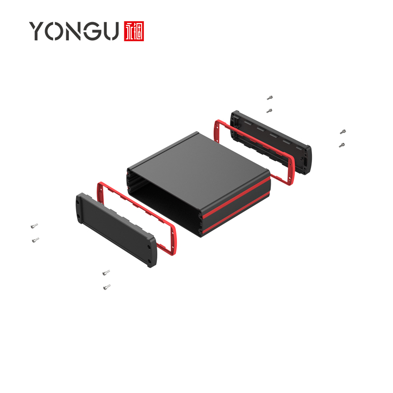
Every IP67 enclosure in our range — extruded bodies with machined end plates, die-cast boxes, unibody CNC shells — seals through the same five interfaces. Design each one deliberately, and the assembly seals; treat any one as an afterthought, and the test tank finds it.
| Sealing interface | Design element | Failure mode |
|---|---|---|
| Cover gasket groove | Groove depth, width, cross-section; seal compression ratio | Seal over- or under-compressed; water at the seam |
| Cover interface & stiffness | Panel thickness, ribbing, flatness of the mating flange | Lid bows between screws; gasket lifts off |
| Fastener layout | Screw pitch, count, position, seating torque | Uneven clamp force; long unsupported runs |
| Cable entry | Gland rating, sealing washer, cable outer diameter match | Water tracks along the cable or through the hole |
| Assembly tolerances | Machining tolerance, batch consistency, first-article inspection | Unit-to-unit variation; seals fine on sample one only |

1. Design the Cover Gasket Groove First
The groove is the single most important dimension in the enclosure, because it converts the gasket material into a seal. Start from the gasket: choose a static O-ring or molded gasket whose cord diameter fits the groove standard practice — then size the groove so the seal is compressed into a defined band, not merely touched.
| Groove parameter | Design rule | Example (2.0 mm O-ring) |
|---|---|---|
| Compression ratio | 15–30% of the cord diameter, 20–25% nominal | Squeezed to 1.5 mm (25%) |
| Groove depth | Cord diameter × (1 − compression ratio) | 1.50 mm |
| Groove width | Cord diameter × 1.2–1.5 (fill, not squeeze sideways) | 2.4–3.0 mm |
| Surface finish | Ra ≤ 3.2 µm on groove and flange faces | Machined, no tool marks |
| Groove geometry | Closed rectangular or dove-tail section; radius at corners | No sharp notches that cut the seal |
The same groove logic applies whether the seal is a molded gasket in a rectangular groove or an O-ring seated in a half-dovetail. What changes is the cross-section — the compression band, the fill factor and the assembly method — but the principle is constant: the groove depth defines the squeeze, and the squeeze defines the seal.
2. Make the Cover Interface Rigid Enough
A perfect groove is useless under a lid that bends. When screws pull the cover down, the panel deflects between fasteners, and the deflection takes the gasket contact away. The cover interface has to stay flat under clamp load, and that is a stiffness problem, not a material problem.
- Panel thickness: our IP67 covers use 3 mm or 5 mm aluminum plate — 5 mm where the opening is large or the load high.
- Ribbing: a stiffening rib or raised land around the perimeter and across the center reduces deflection far more than extra thickness alone.
- Flatness: the flange that mates with the gasket is machined to ≤ 0.05 mm flatness, so the seal sees an even surface — anodizing is masked or controlled on sealing faces so the coating does not build uneven thickness.
- Fastener position: screws sit close to the seal line, never far inside it, so clamping force lands on the gasket, not on the middle of the lid.
3. Lay Out the Fasteners for Even Clamp
Clamping force is the energy source of the seal; the fastener pattern distributes it. The rule of thumb that keeps our IP67 enclosures reliable: a screw every 60–80 mm along the seal line, positioned so no stretch of gasket runs more than about 40 mm unsupported, with corner screws added where the lid tends to lift.
| Enclosure length | Suggested screw pitch | Typical screw |
|---|---|---|
| ≤ 100 mm | 4 screws (corners) | M3 |
| 100–200 mm | 60–80 mm pitch | M3–M4 |
| 200–400 mm | 60–80 mm pitch + center screws | M4 |
Torque matters as much as count. A documented seating torque — tightened the same way on every unit — is what turns a good pattern into repeatable sealing. Our assembly lines torque IP67 covers to a fixed spec, and first articles are opened and re-sealed before a batch is released.
4. Close the Cable Entry Correctly
Every cable that enters the enclosure is a potential leak path. The standard solution is an IP68-rated cable gland whose seal grips the cable jacket and its own body, plus a sealing washer where the gland meets the enclosure wall. Three checks decide success:
- Gland rating: the gland must itself be rated IP68 — an IP67-rated gland is the minimum, and matching the enclosure's immersion test is safer.
- Cable diameter fit: glands are designed for a diameter range; a cable at the small end of the range seals worse than one in the middle of the stated range.
- Hole and wall preparation: the entry hole is machined to fit the gland's sealing washer, with the wall thickness within the gland's clamping range, so the gland seats flat and does not distort under its nut.
For enclosures with multiple entries, our MJ-series outdoor gateways use this exact approach: a sealed body with IP68-rated glands for antenna, power and signal cables, plus a molded gasket on the cover — every path closed deliberately.
5. Hold the Assembly Tolerances
The first four steps live on the drawing; the fifth lives in the shop. Sealing is a batch-level promise: unit one and unit 5,000 must machine to the same groove depth, the same flatness, the same hole positions. That is why we machine IP67 and IP68 enclosures to ±0.05 mm on sealing faces and grooves, run first-article inspection with a coordinate measuring machine, and sample groove depth through every batch. The IP68 test reports on our L- and M-series enclosures — tested by Bureau Veritas to IEC 60529 at 1.5 m immersion — exist because the process, not the sample, is what gets tested.
Design Checklist for an IP67 Aluminum Enclosure
- Seal: static O-ring or molded gasket, 15–30% compression, groove depth and width calculated from the cord.
- Cover: 3–5 mm plate, perimeter ribs, flange flatness ≤ 0.05 mm, sealing faces protected during anodizing.
- Fasteners: 60–80 mm pitch, corner screws, documented seating torque.
- Cables: IP68-rated glands, cable diameter in the middle of the gland range, flat gland seating.
- Process: ±0.05 mm machining on sealing features, first-article CMM, batch sampling, third-party test report.
YONGU IP67 Aluminum Enclosures
The design sequence above is what our IP67 aluminum enclosure range is built on: extruded bodies with CNC-machined flanges and grooves, covers sized to the opening, and glands fitted at assembly. For gateway and outdoor-control applications, the MJ-series IP67 gateway boxes show the full design in production, and the L-series profile enclosures cover the IP67-to-IP68 range with machined sealing features. If your product needs a specific size, cutout or cable layout, the customization and machining service starts from your drawing and confirms the groove, cover and gland design before quoting. Common questions on ratings and sealing are collected in the FAQ page.

IP67 Enclosure Design FAQ
What gasket compression ratio should an IP67 design use?
Static seals typically run at 15–30% compression of the cord diameter, with 20–25% as the nominal design target for reliable sealing without seal fatigue.
How many screws does an IP67 cover need?
Enough to hold the gasket contact along the whole seal line — a practical starting point is one screw every 60–80 mm, plus corner screws, with torque controlled during assembly.
Can I reach IP67 without a gasket groove?
Not reliably. A groove positions the seal, controls its compression and keeps it from shifting during assembly. Sealing without a designed groove leaves compression uncontrolled.
Is an IP67 enclosure automatically IP68?
No. IPX7 is a defined 1 m / 30-minute immersion test; IPX8 is continuous immersion at an agreed depth. A design must be verified for each rating it claims.
What tolerance do the sealing surfaces need?
Flange flatness and groove depth are typically held to ±0.05 mm so the compression ratio stays inside the design window across production batches.
References
IP classifications quoted from IEC 60529:1989+AMD1:1999+AMD2:2013 CSV (Ed 2.2, TC 70); Edition 3 is in its committee-draft stage with a forecast publication date of 2027-12-31. Sealing design values (compression ratios, groove proportions, fastener pitch) follow standard gasket engineering practice as applied on YONGU's IP67/IP68 production lines. For choosing between ratings, see How to Choose IP65 vs IP67 Waterproof Enclosure for Outdoor Electronics and the general IP ratings guide.