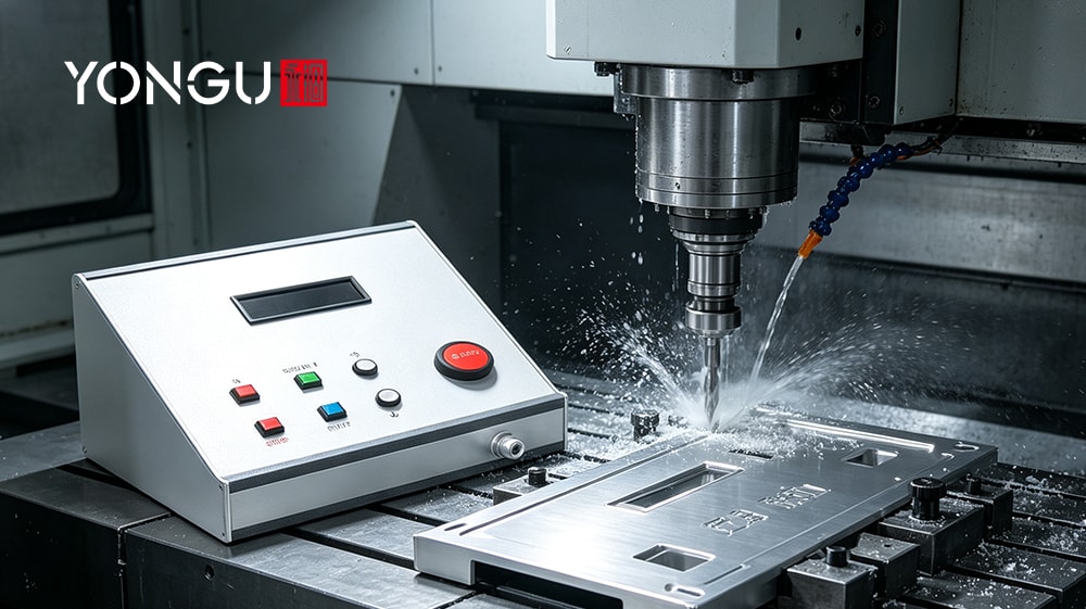
Off-the-shelf extrusion and die-cast boxes cover most projects, but when a product needs an exact shape, tight tolerances or a distinctive finish, a fully custom CNC-machined enclosure is the answer. Milled from billet or plate, it delivers precise cutouts, complex features and a premium look — like the YONGU Audio Console Box N102, a CNC-milled sloped console case for control-panel instruments with changeable size and shape, shockproof corner guards and custom milling.
Materials and Surface Finishes for Machined Enclosures
Aluminum is the default for machined enclosures; the right alloy depends on the environment. 6061-T6 is the best all-round choice with excellent machinability, 276 MPa yield strength, 167 W/m·K thermal conductivity, and anodizes beautifully. 5052-H32 is preferred for marine and coastal designs for its corrosion resistance. 7075-T6 delivers aerospace-grade strength (503 MPa yield) at the cost of machinability and corrosion resistance — it needs a protective coating. 303/304 stainless steel suits medical, food and highly corrosive environments but weighs 2.9× more than aluminum and machines slower. Brass (C360) suits RF hardware, connectors and decorative details. Engineering plastics such as ABS, PC and POM keep weight and cost down for insulating, low-load panels.
| Material | Machinability | Yield (MPa) | Thermal (W/m·K) | Corrosion | Density (g/cm³) | Typical use |
|---|---|---|---|---|---|---|
| AL6061-T6 | Excellent | 276 | 167 | Good (anodized) | 2.70 | Outdoor industrial, general enclosures |
| AL5052-H32 | Good | 193 | 138 | Excellent | 2.68 | Marine, coastal, formed parts |
| AL7075-T6 | Fair | 503 | 130 | Moderate (coated) | 2.81 | Aerospace, high-strength brackets |
| 303/304 SS | Fair | 205–310 | 16 | Excellent | 7.9 | Medical, food, chemical |
| Brass C360 | Excellent | ~250 | 115 | Good | 8.5 | RF hardware, connectors, knobs |
| ABS / PC | Excellent | 40–70 | 0.2 | Good (UV grade) | 1.0–1.2 | Insulating, low-cost, prototypes |
Match the finish to the environment. Type II anodize (5–25 µm) is the workhorse for aluminum — hard, UV-stable, available in colors, and commonly specified against MIL-A-8625; Type III hardcoat (25–75 µm) adds wear resistance for sliding surfaces. Chem film / Alodine keeps the surface electrically conductive for EMI grounding and is the standard for aerospace (MIL-C-5541 / ASTM B921). Powder coating (60–120 µm) gives the toughest cosmetic topcoat; bead blasting plus anodize or mechanical polish delivers the premium look. Machined walls run 1.5–6 mm comfortably from plate stock; keep the material ASTM B209 compliant for critical US programs. Quick-turn anodizing and coating services in the US typically add 2–5 days; see our anodized enclosure selection guide and coastal corrosion guide for detail.
Dimensional Tolerances and Machining Capabilities (2- to 5-Axis)
Know what the machine can hold before you dimension the drawing. Turning (2-axis) produces round bodies, bushings and knobs; 3-axis milling handles prismatic parts — faces, pockets, holes — with standard tolerances of ±0.1 mm. 4-axis adds a rotary table for slots and features on multiple faces in one setup. 5-axis machines angled holes, undercuts and complex cavities in a single setup, which improves accuracy by eliminating re-fixturing error and is the right call for sloped console cases, angled connector ports and contoured panels — exactly the geometry of the CNC-milled N102 console box. Feature size follows tooling: internal threads from M2, slots from 0.5–1 mm width, and logos or lettering at 0.3 mm depth.
| Feature | Standard | Precision (costs more) |
|---|---|---|
| Linear dimensions | ±0.10 mm | ±0.02–0.05 mm |
| Hole diameter | ±0.05 mm | ±0.01 mm |
| Minimum hole Ø | 1.0 mm | 0.5 mm (special tooling) |
| Minimum wall | 1.0–1.5 mm (aluminum) | 0.8 mm |
| Flatness | 0.05 mm / 100 mm | 0.02 mm / 100 mm |
| Surface finish Ra | 1.6–3.2 µm | 0.4–0.8 µm (0.2 µm ground) |
Pay for precision only where it matters: O-ring and gasket grooves, bearing seats, mating flanges and press-fit holes. For grooves, specify depth tolerance ±0.03–0.05 mm; for mating faces, flatness 0.02–0.05 mm/100 mm. Ask for a tolerance map with the drawing so the shop holds printed values rather than nominal dimensions. Post-machining grinding or lapping closes tolerances beyond milling and is worth the cost on sealing surfaces. YONGU operates 3/4/5/6-axis CNC with a professional 5-axis turning machine, holding CNC tolerance ≈ ±0.05 mm and laser cutting ≈ ±0.1 mm — see what you need to know about CNC machines and laser cutting for the full process picture.
Design for Manufacturability: Walls, Bosses, Corners, and Mounting
Good DFM keeps a machined enclosure fast to produce and cheap to finish. The rules below are the geometry standards shops work to every day.
- Walls: 2–4 mm is the sweet spot; 1.5 mm is the practical minimum for a small enclosure. Avoid thick solid walls above 6 mm — they add machining time and material cost without adding value.
- Corners: internal corners inherit the end-mill radius; specify R ≥ 2 mm where possible and never below R1 mm. External corners can be sharp but plan a deburr pass. Add 0.3–0.5 mm allowance where a mating part must seat into a milled pocket.
- Bosses: keep boss height ≤ 3× diameter and add a gusset to prevent vibration and tool deflection; avoid thin isolated bosses near part edges.
- Threaded features: tapped M2–M6 threads need engagement depth ≥ 2× diameter; use HeliCoil or PEM inserts where threads will be repeatedly assembled or the wall is under 2 mm; cored pilot holes save machining time.
- PCB mounting: design M2.5/M3 standoffs or slots with ±0.1 mm position tolerance; leave clearance for component envelopes and cable routes.
- Panel cutouts and cable glands: cut connector openings with 0.2–0.5 mm clearance over the gasket or grommet, and size PG7–PG16 gland holes per the manufacturer's data sheet.
- Tolerance stacking: set the datum on the primary mounting face and reference critical cutouts to it; stacked tolerances across multiple features are the most common cause of rework.
- File prep: submit a watertight STEP (or IGES) solid, one body, cosmetic fillets removed, with a 2D drawing that states datums, critical tolerances and finish. This is what lets CAD/CAM go straight to the machine.
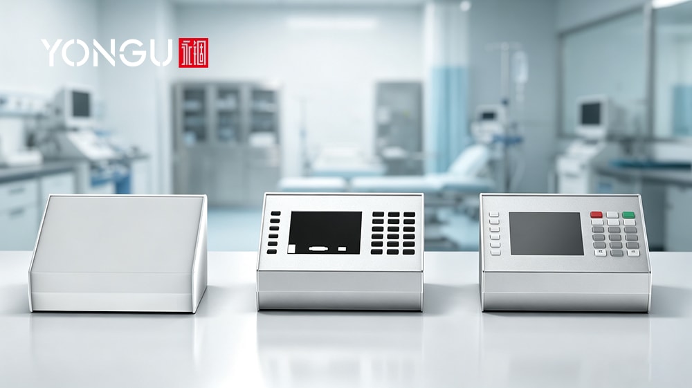
YONGU's full-custom N series follows this playbook — the N104 full custom bending enclosure and the H41 custom CNC service enclosure are machined from customer drawings with customized cutouts, panels and finishes.
Pricing, Lead Times, Prototyping, and Production Scaling
Machined enclosure pricing is driven by five factors, in rough order of impact: machining time (the dominant cost — complex cavities and tight tolerances add hours), material (7075 and stainless cost 2–4× 6061 per kilo), secondary operations (anodize, inserts, laser marking), batch size (setup and fixture cost spread across parts), and tool wear on hard materials. Fixturing is a fixed cost that amortizes with volume — a one-off part may carry $50–200 of setup, while a 500-piece run spreads the same fixture over many parts. Inserts and laser marking add roughly $1–5 per part, and hard anodize adds about 5–15% of part cost. The ranges below are typical US-market figures for a mid-size enclosure (≈200×150×60 mm) in 6061; quote with your supplier.
| Volume | Typical unit price (6061, medium complexity) | Typical lead time |
|---|---|---|
| Prototype (1–10 pcs) | $150–800 / pc | 7–14 days |
| Small batch (25–100 pcs) | $60–250 / pc | 2–6 weeks |
| Production (500+ pcs) | $20–80 / pc (optimized machining) | 3–6 weeks per schedule |
YONGU offers samples in 5–7 days and batch production in 15–20 days with MOQ of 1 pc, which removes the tooling-risk penalty of full-custom work. For US R&D teams, the fastest path is uploading a STEP file with a target tolerance: the shop runs a DFM review, quotes, and ships a prototype before you commit to volume. For an instant estimate, upload the STEP with target tolerance and quantity — most shops return a price band within 24–48 hours and a firm quote after drawing review. Material lead time matters most on 7075 and stainless orders, and fixture reuse drops setup cost on repeat orders. See the advantages of rapid prototyping and our custom CNC machined enclosure line for the prototype-to-production path.
Functional Performance: Sealing (IP/NEMA), EMI/RFI, Thermal, and Fastening
Sealing: machined enclosures seal reliably because the flange can be held flat. Design an O-ring groove to standard proportions (depth ≈ 0.7–0.8× cord diameter, width ≈ 1.2–1.3×), or a gasket groove at 60–80% of uncompressed gasket height so compression lands at 15–25%. Hold flange flatness to ≤ 0.05 mm/100 mm, tighten screws in a cross pattern in two passes, and verify with an IP test per IEC 60529 (IP66/IP67) or NEMA 250. See the NEMA enclosure guide.
EMI/RFI: a machined metal seam is the best shield foundation — 60–90+ dB with continuous contact. Keep mating flanges bare or use chem film so the surface stays conductive, add conductive gaskets or finger stock in a machined groove, and bond the panel at multiple points. Test material per ASTM D4935 and the assembled box per MIL-STD-285 / IEEE 299; our EMI shielding guide and three EMI design principles cover the full layout rules.
Thermal: machined aluminum doubles as a heatsink — 6061 conducts 167 W/m·K. Machine fins with pitch ≥ 1.5–2 mm and 2–3 mm wall thickness on the hot side, bridge heat with TIM pads to a cold wall, and reserve heat pipes or a fan for sealed modules above ~15 W; see aluminum enclosure thermal conductivity.
Fastening: choose HeliCoil for threads that need repeated assembly or repair in aluminum, PEM self-clinching nuts for walls under 2 mm, and heat-set brass inserts when the panel is plastic. Validate on the production line with a torque-to-spec and pull-out check; a typical M3 insert in aluminum holds 60+ kgf. For high-power layouts, the aluminum chassis design guide for signal and thermal management is the reference architecture.
Conversion
Get your next full-custom enclosure moving in 24–48 hours. Download the enclosure design template (STEP/IGES), DFM checklist and machining capability sheet from our downloads page, then send us the four files a quote needs: assembly drawing, material choice, target tolerance, and quantity with expected delivery date. Upload your CAD for a free DFM review and cost estimate — first feedback typically lands within 24–48 hours — or book an engineering review call to walk through sealing, EMI and thermal requirements. No minimum order: prototypes start from a single piece. YONGU supports industrial control, medical, telecom, aerospace, audio and outdoor electronics customers with 20+ years of aluminum enclosure experience — contact us or email [email protected], and browse the full enclosure range while you prepare your files.
FAQ
Which alloys are best for CNC machined full-custom enclosures for outdoor industrial electronics in the U.S.?
6061-T6 is the default: machinable, 276 MPa yield, 167 W/m·K thermal conductivity, and it anodizes well for corrosion and UV resistance. Use 5052-H32 for coastal/marine environments and 7075-T6 only where strength justifies the extra cost and coating requirement.
What dimensional tolerances and minimum feature sizes can I expect from 3-axis versus 5-axis CNC machining?
Both hold ±0.05–0.1 mm standard and ±0.02–0.05 mm precision on linear features. Minimum holes are ~1.0 mm (0.5 mm special), minimum walls 1.0–1.5 mm in aluminum. 5-axis adds angled holes, undercuts and complex cavities in one setup, which improves accuracy and surface quality on contoured enclosures.
How should I design wall thickness, corner radii, and bosses to avoid costly rework or tooling changes?
Keep walls 2–4 mm (1.5 mm minimum), internal corner radii ≥ R1–2 mm (matching end-mill radius), and boss height ≤ 3× diameter with gussets. Set datums on the main mounting face and reference cutouts to it to avoid tolerance stacking.
What are the typical lead times and cost drivers for a prototype versus a small production run of machined enclosures?
Prototypes (1–10 pcs) run 7–14 days at $150–800/pc; small batches (25–100 pcs) 2–6 weeks at $60–250/pc; production (500+) $20–80/pc. The dominant drivers are machining time, material grade, secondary operations, batch size and tool wear.
How can I achieve an IP66/IP67-rated seal on a machined metal enclosure and what gasket details matter most?
Machine an O-ring or gasket groove to 60–80% of uncompressed gasket height (15–25% compression), hold flange flatness ≤ 0.05 mm/100 mm, tighten in a cross pattern in two passes, and verify per IEC 60529 or NEMA 250. Groove depth tolerance ±0.03–0.05 mm is the detail that makes or breaks the seal.
What practical EMI/RFI shielding options exist for machined enclosures and how are they tested?
Keep flanges bare or chem-filmed for conductivity, add conductive gaskets or finger stock in machined grooves, and bond panels at multiple points — this typically yields 60–90+ dB. Test planar material per ASTM D4935 and the assembled enclosure per MIL-STD-285 / IEEE 299.
What thermal management strategies work best for high-power electronics inside a machined aluminum enclosure?
Use the machined aluminum wall as a heatsink with fins (pitch ≥ 1.5–2 mm), bridge hot components to the cold wall with TIM pads, and add heat pipes or a filtered fan for sealed modules above ~15 W. 6061's 167 W/m·K conductivity makes the body itself the most reliable thermal path.